
Glenn Curtiss Aviation Engine Valvetrain Developments
Jim Cowart, US Naval Academy
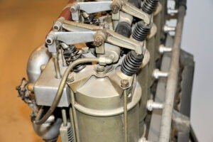
Curtiss Model S valvetrain detail at the Curtiss Museum in Hammondsport, New York. (Photograph by J. Cowart, from the author’s collection).
Glenn Curtiss Aviation Engine Valvetrain Developments
Glenn Curtiss is widely known as an aviation pioneer during the early days of flight who developed key aviation technological advancements. In addition to numerous aircraft control and airframe innovations, his engines were also quite progressive and developed at a rapid rate during his active years of flight.
Two excellent articles have previously outlined Glenn Curtiss’ engine developments. K. M. Molson, curator at the National Aviation Museum in Ottawa, Canada, wrote a Curtiss engine overview and summary in 1966.[1] L. Rinek, published two papers in the mid-1990s outlining Curtiss aviation engines.[2, 3] While these authors make mention of Curtiss’ engine valvetrain developments, detail is not provided. For those today who look carefully at a Curtis engine on display, it is likely that some unique valvetrain features will be noted. For example, the widely used OX-5 engine in the Jenny aircraft has an interesting push rod appearance. The objective of this article is to focus on Glenn Curtiss’ aviation engine valvetrain developments in greater detail as they were a key factor in the increasing performance that Curtiss was able to achieve over his early years of flight.
In this article, schematics will be provided that were developed by the author in order to provide conceptual insights. This will be followed by pictures of related Curtiss engines. For each major development, descriptions and discussion will place each new development in context. The author has enjoyed pursuing this study. He recalls looking at many Curtiss engines, without initially understanding from the ‘outside’ how they worked. Hopefully this article will enliven the understanding of those who have also been interested in Curtiss engines in detail.
EARLY AVIATION ENGINES
(F-Head Valvetrain)
Glenn Curtiss began building motorcycles in 1901. He originally purchased cast engine cylinders, then went on to work with a local foundry to produce his own engine cylinders and blocks. The conventional automotive and motorcycle engines at this time had separate cylinders bolted to a crankcase block. The combustion chamber and valve configuration at this time was commonly the ‘F-head’ (due to its roughly F shape with both the intake and exhaust valve heads horizontally offset from the main cylinder vertical line). Engines at this time had low compression ratios due to the low octane nature of early gasoline, thus the combustion chamber volumes were quite large. The offset valves allowed for easy-simple actuation from a camshaft that was generally located in the cylinder block. For Curtiss and many others, often the intake valve was not mechanically actuated, but rather ‘automatic.’ The falling action of the piston during the intake stroke would automatically (by cylinder suction) open the intake valve and allow fresh air and fuel to enter. Figure 1 shows a schematic of this F-head engine.
In looking at this figure it is seen that the Intake is Over the Exhaust (IOE). Generally a light spring would keep the intake valve closed during compression, combustion and expansion when the cylinder pressure is above atmospheric or intake manifold pressure. When a vacuum formed during the intake stroke due to the falling piston, it would pull open the intake valve allowing fresh air and fuel to enter the cylinder. For a low speed engine, which was common during the first decade of the twentieth century, this arrangement worked fine. Once the piston reached Bottom Dead Center (BDC), the piston reversed direction and the compression stroke began (middle image in Figure 1). This decreasing cylinder volume caused the in-cylinder pressure to rise above atmospheric (or intake) pressure . . .
This article costs $5.00 to download - or it's free for AAHS members.
Already a member? Sign in to download for free.